Products
Design and Seismic Response Analysis for Multiple Buildings with Large Podium Using Inter-story Isolation Technology
1.Introduction:
Land tension problems in recent years continue to intensify in large city, like Beijing, Shenzhen,Guangzhou and Shanghai. At the same time, the rapid development of subway and rail transit lead to the gathering effect of the crowd. The land in the subway station and vehicle parking section and other nearby land is high cost. The solution of this contradictory problem can be perfectly solved by multiple buildings with large podium. The large space of bottom can be used as a commercial plaza, and the upper tower building can be used as office buildings, residential, hotels and so on. This kind of building scheme maximizes the use of construction land, by providing more available space for urban development and satisfying the owners' greatest benefit of the building, so the structure has been widely used.
Rigid transfer floor and inter-story isolation floor used in the bottom large platform. The abrupt stiffness change would occur in the connection, if adopting the steel reinforced concrete conversion structure. Under the external load, the stress of the structure is very likely to produce stress, and even concentrated damage. And the structural integrity is poor, and its vibration is complex and diverse and it is more likely to occur coupled plane-torsion vibration. Different from the general rubber bearing which rubber layer made of dozens of thin layers, thick rubber bearing by reducing the number of layers to increase the thickness of single layer makes vertical stiffness significantly reduce. This kind of bearings caused a certain attention in recent years in the earthquake engineering construction of three-dimensional base isolation system.
It is found that the vertical mechanical properties of the thick rubber bearing are quite different from those of the general bearing theoretical formula and need to modify. thick rubber bearings structure can be directly applied to the formula of ordinary rubber bearing isolation, because the difference between the horizontal mechanical properties is not great. The nuclear power plant adopts the thick rubber bearings.
In this paper, Shanghai Xinzhuang is taken as an example to design and analyze the thick rubber bearings as transfer floor, and taken the impact of the environmental vibration under the large podium structure into consideration.
1.Design Process
Figure 1 is the flow chat of isolation design. The key steps are described below.
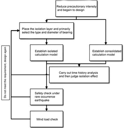
Figure 1 Flow Chat of Isolation Design
2.Engineering Situation and Consolidation Calculation Model
Based on the project design of the upper cover of Xinzhuang hub, the eastern part of the whole development project is taken as the calculation and analysis model. There are two 12-storey multiple buildings(T6 and T7) on the large podium, as well as four 6-storey multiple buildings(T11, T12, T13, T14). And the large podium takes advantage of concrete frame structure, and the upper house is with frame and shear wall structure. The 6-storey residential building is located above Metro Line 5 and 12-storey Line 17.
The scheme model of rigid transfer floor was established by using Midas software. The three-dimensional view of the whole structure is shown in figure 2. As T11 - T14 structure is similar, the following design and calculation results mainly discuss the T11, T6, T7 multiple buildings.

Figure 2 3D View of Calculation Model
3.Model Design
3.1.Layer Isolation Design
Using thick rubber bearings can not only play a role in isolation, but also reduce the vibration effect from the upper multiple buildings with large podium. Schematic diagram of the upper cover utilizing the transfer floor is shown in figure 3.

Figure 3 Schematic Diagram of Isolated Structure
3.1.1.Layout of isolation Bearing
Considering to reduce the vibration of the subway on the comfort of the upper multiple buildings, the geometrical parameters and mechanic properties of the thick rubber bearing products are used to calculate parameters, as shown in table 1 and table 2.
| Physical Dimension | LRB900-170 | NRB900 | LRB800-150 | NRB800 |
| External Diameter(mm) | 920 | 920 | 820 | 820 |
| Rubber Cover Thickness(m) | 10 | 10 | 10 | 10 |
| Effective Diameter(mm) | 900 | 900 | 800 | 800 |
| Lead Diameter(mm) | 170 | - | 150 | - |
| Internal Layer Thickness(mm) | 15 | 15 | 13 | 13 |
| Total Thickness of Inner Rubber Layer(mm) | 225 | 225 | 208 | 195 |
| Clear Height(mm) | 334.2 | 334.2 | 315 | 298.2 |
Table 1 Shape Parameter of thick rubber bearings
| Mechanic property | LRB900-170 | NRB900 | LRB800-150 | NRB800 |
| Designed Compressive Stress(MPa) | 8.0 | 8.0 | 8.0 | 8.0 |
| Vertical Stiffness(kN/mm) | 1270 | 1239 | 1128 | 1162 |
| Tensile Strength(MPa) | 1.0 | 1.0 | 1.0 | 1.0 |
| Stiffness before horizontal yielding(kN/mm) | 19.993 | - | 17.087 | - |
| Stiffness after horizontal yielding(kN/mm) | 1.538 | - | 1.314 | - |
| Horizontal Equivalent Stiffness(kN/mm) | 2.342 | 1.529 | 1.992 | 1.393 |
Table 2 Mechanic Property of thick rubber bearings
3.1.2.Design Check of Isolation Layer
In the above layout, the compressive stress of the bearing under gravity, the eccentricity and the yield ratio of the isolation layer are checked. Compared with ordinary rubber bearings, thick rubber bearings should be carefully selected because of thick rubber layer which resulting in small compressive stress that generally controlled at 8. The compressive stress of each bearing under gravity meets requirements of the bearing design, and the eccentricity rate is less than 3% in accordance with the requirements of "Shanghai Code for Seismic Design of Building"(DGJ 008-9-2013). The results are summarized in table 3.
| T6 | T7 | T11-14 | |
| Maximum Compressive Stress(MPa) | 6.18 | 6.72 | 5.74 |
| Average Compressive Sterss(MPa) | 4.52 | 4.67 | 4.56 |
| Eccentricity Rate X | 1.01% | 0.40% | 1.40% |
| Eccentricity Rate Y | 2.50% | 2.19% | 1.35% |
| Yield Radio | 2.8% | 3.2% | 2.8% |
Table 3 Design Check of Isolation Layer
3.1.3.Structural Period
The isolation structure mainly place isolation layer to extend the structural period, so as to reduce the action of earthquake. Compared the basic period of the isolated structure and the consolidated structure, the isolation effect of the isolated structure can be roughly controlled. As comparison of table 4, the extension effect of structural period is remarkable.
| NO. | Period Before Isolation(s) | Period After Isolation(s) |
| T6 | 1.4085 | 2.7392 |
| T7 | 1.2692 | 2.7466 |
| T11 | 0.7862 | 2.2055 |
Table 4 Comparison of Natural Period
3.2.Precautionary Check Under Earthquake Action
Time history analysis is used separately in isolated and consolidated structures to check seismic effect under earthquake action.
3.2.1.Input Seismic Situation
Based on “Shanghai Code for Seismic Design of Building”, SHW1 ~ SHW2 are artificial wave and SHW3 ~ SHW7 are natural wave. Figure 5 (a) is response spectra of seven wave. And figure 5 (b) is the comparison between time history spectrum and code spectrum. It is founded that the difference between time history spectrum and code spectrum at the structural period point can be controlled within 20%.
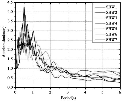
(a)Response Spectra

(b)Comparison of Response Spectra and Time History Spectra
3.2.2.Seismic Effects Comparison
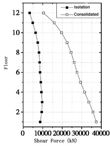
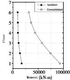
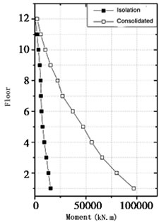
Input 100gal acceleration(seven degree fortification) and carry out time history analysis of the isolated structure and consolidated structure. The main purpose of the comparison is to measure the isolation effect by comparing response of isolated structure and consolidated structure. The comparison of multiple buildings T6, T7 and T11 shear and interlayer torque is shown in figure 6-8. Both the shear force and the interlayer torque, simplified analysis, are the average value calculated by seven times records and the software uses a one-way seismic input.
By comparison, it can be seen that the shear and overturning moment significantly reduced using isolated technology. Compared with the consolidated structure, the upper response spectrum of the isolated structure is smoother and shows excellent seismic performance.
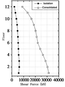
(a)Shear Force in X Direction (b) Shear Force in Y Direction


(c) Overturning Moment in X Direction (d) Overturning Moment in Y Direction
Figure 6 Seismic Response Comparison of T7


(a)Shear Force in X Direction (b) Shear Force in Y Direction

(c) Overturning Moment in X Direction (d) Overturning Moment in Y Direction
Figure 7 Seismic Response Comparison of T11


(a)Shear Force in X Direction (b) Shear Force in Y Direction

(c) Overturning Moment in X Direction (d) Overturning Moment in Y Direction
Figure 8 Seismic Response Comparison of T6

Figure 9 Horizontal Seismic Coefficients of Tower Building
3.3.Structural Safety Check Under Earthquake Action
Input seismic peak 220gal and then carry out time history analysis to test the response of isolated structure under the rare occurrence earthquakes for verifying the safety of the isolated structure under strong earthquakes.
3.3.1.Displacement Check of Isolation Layer
Based on “Shanghai Code for seismic Design of Building”, the limited horizontal displacement of bearing should not exceed half of effective diameter of bearing and two times total thickness of the rubber.
The limited displacement is 450mm for the T6, T7 multiple buildings and 400mm for T11-T14 multiple buildings. From the calculation results, the displacement of the isolation layer at rare intensity meets the requirement and the maximum displacement calculation of isolation layer is as shown in table 5.
| NO. | T6 | T7 | T11 | T12 | T13 | T14 |
| Maximum Displacement | 222 | 215 | 221 | 218 | 217 | 218 |
Table 5 Maximum Displacement of Isolation Layer
3.3.2.Tensile Stress Calculation of Bearings
The load combination using to calculate tensile stress of bearings is:
1.0 dead load±1.0 horizontal earthquake force - 0.5 vertical earthquake force, and the expression of load combination is:
1.0 D ± 1.0 Fek - 0.5 × 0.4 (1.0D + 0.5 L) = 0.8 D - 0.1L ± 1.0 Fek (1)
Based on “Shanghai Code for seismic Design of Building”, the tensile stress of rubber bearings in the vertical and horizontal earthquakes which is rare occurrence should not be greater than 0.5MPa. It can be calculated that the maximum tensile stress of isolation bearing 0.3MPa could be obtained in the corner of the multiple buildings. The results are shown in the table 6.
| NO. | T6 | T7 | T11 | T12 | T13 | T14 |
| Maximum Tensile Stress | 0.30 | 0.30 | 0.09 | 0.09 | 0.09 | 0.08 |
Table 7 Maximum Tensile Stress in Rare Intensity
3.4.Wind Load Check
According to the wind load information, the basic wind pressure of the construction site (50 years) is 0.55kN/m2, and the site roughness is C class. In the Midas, the total shear forces in the X and Y directions are calculated as 5344 kN and 7462 kN respectively.
Based on “Code for seismic Design of Building”, the total horizontal force produced by the wind load of the isolated structure should not exceed 10% of the total structural gravity. The total structural weight is 2453000 kN. The total horizontal force generated by the wind load is less than 10% of the total gravity and meets the requirements.
In order to meet the requirements of wind load and micro vibration, the isolation layer must meet the requirement of bearing capacity before yielding. Based on “Technical Specification for Seismic-isolation with Laminated Rubber Bearing Isolators (CECS126:2001)”, the wind resistance device shall be tested as follows:
YWVWK ≤ VRw (2)
In the formula(2), VRw is the horizontal load of device. Take designed valve of the yielding load, when the the wind resistant device is not alone set. Yw is partial safety factor for load. Ywk is standard value of horizontal shear force of isolation layer.
The calculation results of the wind load of each multiple buildings are listed in table 7. From the comparison, the structure meets the wind load check requirement.
| NO. | T6 | T7 | T11-T14 |
| Shear Force Under 1.4 Times Wind Load X | 1406 | 1560 | 806 |
| Shear Force Under 1.4 Times Wind Load Y | 2335 | 3934 | 811 |
| Yield of Isolation Layer(kN) | 3060 | 5440 | 1500 |
4.Conclusion
In this paper, the structure of the multiple buildings with large podium (Shanghai Xinzhuang subway) is taken as an example. We design the scheme of transfer floor and the isolated structure of thick rubber bearing, and show the design process and describe the key steps in detail. Through the calculation and analysis, we can get the following conclusions:
(1)The design process of isolated structure using thick rubber bearings is similar to that of traditional rubber bearing. The design difficulty lies in the fact that the vertical stiffness of the thick rubber bearing is small (the design pressure is less), but the horizontal stiffness is roughly the same as that of the ordinary rubber bearing. Therefore, the vertical load capacity and the horizontal isolated effect also should be considered.
(2)Although the design of the thick rubber bearings has the above difficulties, the calculation shows that the good isolation effect can be achieved by optimizing the design. Horizontal damping coefficient which is less than 0. 4 can meet the requirements of isolation effect that reduce one intensity of the upper isolation layer in existing norms.
(3)The safety of the earthquake action(the maximum displacement of the isolation layer and tensile stress), wind resistance and micro vibration can meet the requirements.
(4)Due to the small vertical stiffness of the thick rubber bearing, the structure has the possibility of excessive overturning under strong earthquakes. The calculation shows that under the action of rare occurrence earthquakes, the maximum tensile stress of transfer floor of multiple buildings is 0.30MPa, which is less than the limited requirement. It is shown that the overturned and rocking problems of the seismic structure with thick rubber bearing is not significant.
Inquiry for Our Product
Zaoqiang Dacheng Rubber Co., Ltd.
E-mail:
sales@bridgebearing.org
When you contact us, please provide your detail requirements. That will help us give you a valid quotation.